Welcome to Our Community

Some features disabled for guests. Register Today.

Standalone Torch Height Controller for CNC Plasma Cutting

Discussion in 'Laser Cutters' started by Retsaj, Oct 7, 2020.
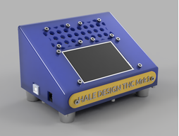
  1. bpresten3

    bpresten3 New
    Builder

    Joined:
    Feb 27, 2024
    Messages:
    5
    Likes Received:
    0
    I have a question I see the drawing you have shows a 50:1 coming from the plasma cutter voltage divider. What if your plasma cutter has a 1:1 output how do you suggest wiring to the thc. Would you still install the cap?
     
  2. Drell8345

    Drell8345 New
    Builder

    Joined:
    Mar 22, 2024
    Messages:
    1
    Likes Received:
    0
    I am building the THC controller and have hit a snag with the screen I have the screen you have stated and uploaded the gui file from the site, but I keep getting the same error message on the screen "File Version is Too low" I am not so good on Gui and I am stuck I have tried different SD cards but still get the same error
     
  3. Peter Van Der Walt

    Peter Van Der Walt OpenBuilds Team
    Staff Member Moderator Builder Resident Builder

    Joined:
    Mar 1, 2017
    Messages:
    14,865
    Likes Received:
    4,283
    Note connecting and disconnecting a powered stepper motor from its driver -even by relay - will ruin your stepper driver. Not if, but when.
     
    David the swarfer likes this.
  4. Peter Van Der Walt

    Peter Van Der Walt OpenBuilds Team
    Staff Member Moderator Builder Resident Builder

    Joined:
    Mar 1, 2017
    Messages:
    14,865
    Likes Received:
    4,283
    Hook up an oscilloscope watch the peaks of all the back EMF and cable inductance dumping back into the drivers at the time it switches. Learn more here

    "10ms" has no bearing here either - stepper drivers doesn't run on AC frequencies, nor are their phases synced. TMC2160s has a 12Mhz clock - not 60Hz. By your (still invalid, there is a better way) theory you'd need a switchover time of under 12,000,000th/sec (12Mhz) and if you are off by half that between switches you could hit the sine wave at opposing times making things even worse. Not to mention that the two drivers won't be in sync (or even perfectly 180deg out of sync) to begin with

    What do you think flows between the driver and stepper motor other than Power? Not just plain DC or AC either - a complex chopper stepped pseudo wave at set current and variable voltage. They are constant current devices, you break the connection, resistance becomes infinate, constant current driver tries to compensate. You have to think about what this actually is. Its not a Mains powered UPS - 10ms switching is irrelevant.

    Tolerance = for occational mistakes like a wire break, not daily use multiple times per job.

    Now, the RIGHT way to do this would have been to keep PSU>DRIVER>MOTOR as a unit. Switch the SIGNALS :) relay on step/dir/enable between controller and THC

    Same as how the commercial THCs do: Internal relays switch the control signals, long before it gets to the Driver, exactly so you don't cause motor wire disconnect/connects - they really are bad for your drivers!

    [​IMG]
     
    #64 Peter Van Der Walt, May 14, 2024
    Last edited: May 14, 2024
    David the swarfer likes this.
  5. Peter Van Der Walt

    Peter Van Der Walt OpenBuilds Team
    Staff Member Moderator Builder Resident Builder

    Joined:
    Mar 1, 2017
    Messages:
    14,865
    Likes Received:
    4,283
    Second one, but I would not switch GND. Leave it connected (safer all round than floating grounds and alternative ground paths).
    Just DIR/STEP/ENABLE
    I still suspect the out-of-band THC will cause Z-height issues but thats something one may be able to work around with touchoff probes rezeroing etc - will have to see how it plays out.
     
  6. cnc-trucker

    Builder

    Joined:
    Mar 20, 2024
    Messages:
    13
    Likes Received:
    11
    UPDATE: THE DIVE ISSUE I MENTIONED BELOW HAS BEEN CORRECTED.

    Jeramiah, in one of your posts in this forum topic, you stated that if anyone could integrate your THC into a GRBL machine, you would like to know how they did it. Well, I have done it...
    You can check out the new source code (with due credit to you, of course!) at my GitHub fork of your repository.

    Basically, I re-wrote your code into an ISR -- the program monitors the ARC-OK signal and, when received, triggers an interrupt to assume control of the Z-axis during the cut. When not actively cutting, the program simply passes the Z-axis pulses on to the stepper motor driver from the GRBL controller un-altered.

    I also changed the plasma voltage mapping you used (to accomodate Everlast's 0-3 volt arc voltage range) to map(analogRead(PLASMA_INPUT_PIN) + CalibrationOffset, 0, 1023, 0, 16500), so now it works on the Everlast 62i/ 82i/102i cutters without having to resort to full arc voltage and a home-brew voltage divider.

    In the process of re-writing your code, I fixed many minor coding issues that kept the Nextion display from being updated and -- as a side result -- kept values from being stored in the EEPROM. Nextion has changed a lot of their firmware, and I believe that they simply changed the methods you used to pass values to the display; the EEPROM issues were caused by a conflict between data types.

    I changed the EEPROM address allocation routine to use pointers to assign and pass the EEPROM addresses instead of the values themselves, then passed that pointer to other functions (EEPROM.readInt(*addressPage1) instead of EEPROM.readInt(addressPage1); this saved on memory usage, too.

    As for the Nextion functions, most of them require that values passed to them be cast to uint32_t instead of just passing the native int value -- once I cast them properly, and put the serial initialization code into the "Splash Screen" pre-initialize event code (you forgot to in the HMI file in your repository), the display functioned properly and showed/ stored data as it should.

    As I said, the THC works well now -- with only one issue. At the very end of the cut, when the THC is passing control back to GRBL, it seems to want to dive into the metal -- I believe that it relates to your code block
    Code:
      //after cut reset height
      pos = 0;
      //do move
      stepper.moveTo(pos);
      while (stepper.distanceToGo() != 0) {
        stepper.run();
      }
    
    at the end of the height following routine. I saw no initialization of the torch height by the THC at the start of the interrupt, so I believe that it simply doesn't know where to reset the height to when it finishes. I have corrected that problem now, though, and the THC works very well.

    Here is a short video of this THC in action, attached to this post. I've also attached a wiring diagram for an entire Mega 2560-based GRBL machine, complete with limit switches & this THC.
     

    Attached Files:

    #66 cnc-trucker, May 31, 2024
    Last edited: Jun 29, 2024
    mleaming and Giarc like this.
  7. Windvane

    Windvane New
    Builder

    Joined:
    Jun 20, 2024
    Messages:
    2
    Likes Received:
    0
    I'm getting the same error message. Have you had any success in solving the issue?
     
  8. cnc-trucker

    Builder

    Joined:
    Mar 20, 2024
    Messages:
    13
    Likes Received:
    11
    Windvane,

    If you will go to the link in my post, you will find the updated files for this THC to run it along with GRBL as an interrupt-driven addition to GRBL's Z-axis. To answer your question, though, you have to download the latest Nextion Editor and open the .hmi project file. Go to "Device ID" on the top menu bar -- from there you can select your device and rebuild the project with the latest version.

    As I mentioned in my post (#66, above), there were a couple of errors in Retsaj's files that kept them from displaying data properly. Also, the display Retsaj used is no longer available -- I used the NX4832K035-011, available from Amazon.

    Let me stress, in order to build the updated THC, you need to go to my Git repository and get the files I have there -- they include a current .hmi project file updated for the latest version. If you are using a device different from the NX4832K035-011, you will still need to change the device ID in the Nextion Editor.
     
    #68 cnc-trucker, Jun 29, 2024
    Last edited: Jun 29, 2024
  9. Windvane

    Windvane New
    Builder

    Joined:
    Jun 20, 2024
    Messages:
    2
    Likes Received:
    0
    Thank you CNC Trucker! I'll give it a try.
     
  10. cnc-trucker

    Builder

    Joined:
    Mar 20, 2024
    Messages:
    13
    Likes Received:
    11
    You might want to know -- I ran into a problem with the THC; don't get me wrong, it works great on straight cuts -- but 5 times last night while cutting some trailer parts out of 1/2" mild steel at 80 amps, it caused GRBL to disconnect. I ended up disconnecting the THC completely and finishing up without it.

    I haven't had time to really do any troubleshooting -- all I know at this point is that 5 times, when the cut reached a certain (and identical every time) coordinate, GRBL disconnected and it took multiple tries to re-connect.

    I tried disconnecting the ARC OK input to the THC to de-activate it and force the THC to pass the Z-axis commands straight through from GRBL to the stepper driver, but it did it again twice.

    Finally, pressed for time to complete the job (I have a 60-ton 9-axle trailer down waiting on these parts), I finally just ran my Z-axis outputs straight to the Z-axis stepper driver like normal and powered off the THC. GRBL did fine after that.

    I have a hunch that there is some sort of EMI leakage or voltage spike making it through somewhere -- although I don't know where; every input into GRBL (motor cables, limit switch cables, probe cable, USB cable, CNC cable from the cutter, power line which has an EMI filter on it) is either internal in the shielded metal cabinet, or shielded and/ or optically isolated from the outside.

    It could also be something in my code, but I seriously doubt it.

    The funny thing is that, in every instance, it was during the start of a G2 arc movement at F100 -- since the THC doesn't account for anything other than straight movement, this may be something for me to look very closely at.

    John

    PS: I have to say that, if you haven't installed limit switches and enabled homing -- DO IT!! Being able to just re-home the machine without losing my work coordinates every time GRBL disconnected saved my bacon last night -- all I had to do was edit my G-code to the point where it disconnected, and run the job. Limit switches and homing REALLY make life easier for the CNC operator!!
     
    #70 cnc-trucker, Jul 2, 2024
    Last edited: Jul 2, 2024
  11. David the swarfer

    David the swarfer OpenBuilds Team
    Staff Member Moderator Builder Resident Builder

    Joined:
    Aug 6, 2013
    Messages:
    3,430
    Likes Received:
    1,907
    likely unrelated because the THC is not reading the Gcode at any time, right?
     
  12. cnc-trucker

    Builder

    Joined:
    Mar 20, 2024
    Messages:
    13
    Likes Received:
    11
    No, not related at all, I think -- other than that when it starts the G2 arc movement, the torch voltage goes up because of the slow-down; I think that could be the cause of this -- the voltage could be spiking above what the Arduino can handle. And, now that I think about it, the divided arc voltage from the plasma is the only "un-filtered" line coming into the cabinet -- maybe the spike is just a high enough enough transitory EMI to disrupt the main Mega 2560 MCU (it likely disrupts the Uno THC, too -- but I wouldn't see it because the Mega craps out first). Perhaps I can add a shielding box around the THC and shielding around the divided arc voltage line inside the cabinet to try to prevent that?

    As I said, I haven't had time to trouble-shoot it -- now that I have the parts cut, I will be spending the next 2 days at our drop yard with the service truck, welding them into the trailer neck. And we just went into an "Extreme Heat Advisory" here in Southern Oregon... fun, fun, fun!

    No David, GRBL does just what it is supposed to do -- it seems that an outside influence caused it to crap out; once I was able to re-connect without the THC, it finished the job without a hitch.
     
    #72 cnc-trucker, Jul 3, 2024
    Last edited: Jul 3, 2024
    David the swarfer likes this.
  13. cnc-trucker

    Builder

    Joined:
    Mar 20, 2024
    Messages:
    13
    Likes Received:
    11
    Well, David, now that I have the trailer back up & running, I've had time to do some in-depth trouble-shooting on this issue.

    I built a Mega/ Uno/ GRBL simulator, identical to my plasma table in all respects, in SimulIDE that works very well -- I can connect to any of the senders and watch what the "machine" is doing while interacting with it at the same time. I found that the root of the problem is the Uno being used for a THC -- to put it bluntly, it simply cannot handle the pressure of fluctuating arc voltages/ spikes that occur when it starts the G2 arc movement, when the torch changes direction/ speed relatively quickly.

    The Uno kept up wonderfully on all straight cuts, adjusting torch height to keep torch voltage to within 1.5 volts actual voltage. BUT -- when the G2 arc movement initiated, with it's resulting slowdown in cutting speed and changing deltas, torch voltage began fluctuating in a 2-10 volt range (calculated raw voltage). The Uno managed to keep up for the first few samples, but once the actual torch voltage increased or decreased by more than 6 volts, the Uno became overloaded with "torch up/ torch down" calls that it simply gave up and reset. Once it reset, with it being connected to the Mega main controller through the Z-axis wires, it was a cascading failure that knocked the Mega off-line too. The resulting double reset couldn't be recovered from until both the Uno & Mega were back on line with GRBL completely reset as if it were power cycled.

    The original author, Hale, switched from a Uno to a Mega after a short time -- and I have a hunch that this is why. I have a second Mega that I am going to use as a test-bed, and re-create my interrupt-driven version of my Uno THC sketch -- we'll see if the Mega gives better results.

    Unfortunately, no one seems to know how to get in touch with the original developer -- so I have had to figure out the code on my own. What I did accomplish is excellent -- especially for a 66-year old who hasn't even looked at the K&R C language since his college days in his 20's! But maybe I haven't lost it yet -- we'll see with the Mega.

    John
     
    David the swarfer likes this.
  14. David the swarfer

    David the swarfer OpenBuilds Team
    Staff Member Moderator Builder Resident Builder

    Joined:
    Aug 6, 2013
    Messages:
    3,430
    Likes Received:
    1,907
    seems you need higher clock speed, maybe an ESP32 can keep up (240mhz instead of 16mhz on the atmels)? only caveat is to ignore the onboard ADC and use an external I2C ADC.

    also worth a try it to force the cut start points to avoid arcs. you can do this in fusion360 but setting a start point for each shape. could be a bit of a pain for something with a lot of holes >-:
     
  15. cnc-trucker

    Builder

    Joined:
    Mar 20, 2024
    Messages:
    13
    Likes Received:
    11
    David, it is funny that you mention the external ADC; I just completed a new THC sketch that uses the ADS1115 ADC instead of the on-board ADC. You may be right on the clock speed, but I am thinking that a Mega, un-burdened with any other processes, may be able to keep up (at least for my needs). The biggest issue with the Uno was memory corruption that caused the melt-down -- the Mega has more memory and a faster processor (even though it's clock speed is still 16 mHz, it utilizes a wider data bus). Also, by taking the ADC functions off-board, that will reduce the computation load on the Mega. So, we'll see what happens, I guess.

    John
     
    David the swarfer likes this.
  16. richard yates

    Builder

    Joined:
    Apr 27, 2015
    Messages:
    11
    Likes Received:
    1
    I have a question about the ARC and OK connections showing connected to the Arduino UNO.ARC is going to ground and OK is going to pin 4. What is this for? I am new to arduino and THC so I am trying to understand before I start building.

    upload_2024-7-27_18-56-38.png
     

    Attached Files:

  17. cnc-trucker

    Builder

    Joined:
    Mar 20, 2024
    Messages:
    13
    Likes Received:
    11
    :) LOL! It's one word -- sort of -- and it's a switched ground on the Arduino boards. Ground to one pin on your CNC connector, the other CNC connector pin goes to the Arduino pin.

    Honestly, Richard -- I have given up on this THC; it was too flawed and the Arduino boards are just too lacking in capability.

    I have just finished re-building my table for LinuxCNC with the old Arduino Mega 2560 now running a "brain dead" THC through QtPlasmaC in Mode 2 (up & down inputs right into LinuxCNC, which handles all of the Z axis adjustments natively).

    LinuxCNC was much easier to build, and offers G-codes/ M-codes that GRBL cannot offer due to the limitations of the boards. And, to be completely objective about it, I think that LinuxCNC does a better job all-around -- it easily interfaces with a THC, and offers things like ClassicLadder which allows you to run a "status light mast" and other nice additions to a table/ mill/ lathe/ etc. And it doesn't cost an arm & a leg (unless you go with the Mesa boards & Mach3/4) -- my table uses 2 parallel ports connected to 2 SainSmart ST-v3 breakout boards. It runs on an old Dell Optiplex 755 that I salvaged from my "better keep it for future use" pile. The whole conversion cost me a total of $60
     
  18. richard yates

    Builder

    Joined:
    Apr 27, 2015
    Messages:
    11
    Likes Received:
    1
    Thank You for the update. I started with LinuxCNC back before Arduino and GRBL. I will look into this. Thank you for the information.
     
  19. cnc-trucker

    Builder

    Joined:
    Mar 20, 2024
    Messages:
    13
    Likes Received:
    11
    LinuxCNC has come a long way; they are up to v2.9.2 now, and have introduced the QtPlasmaC module completely dedicated to plasma cutting. The biggest drawback to it is the necessity of the computer having a working parallel port(s) -- computers aren't built with them now days -- and the user's ability/ willingness to run Debian Linux.
    My machine is running Debian 12 (Bookworm) with the 5.4.258-rtai-amd64 RTAI kernel; it has one native parallel port, and a second one on a PCIe expansion card. I already had most of the components, and am already very comfortable running/ programming Linux, but even if someone had to buy all of the components they could get it all for less than $250 I would imagine.
    John
     
  20. richard yates

    Builder

    Joined:
    Apr 27, 2015
    Messages:
    11
    Likes Received:
    1
    I am very familiar with Linux, actually prefer it over windows. Could you post a simple wiring diagram on how you set it up with Arduino mega and the BOB.
     
  21. cnc-trucker

    Builder

    Joined:
    Mar 20, 2024
    Messages:
    13
    Likes Received:
    11
    Stainsmart_Breakout_ST-V3_Board.jpg
    I'll do you one better than that -- check out my Git repository at GitHub - ccwtruck/LinuxCNC-4x4-PlasmaTable: Complete working LinuxCNC 54" x 60" Plasma Table Control Software With Arduino Mega 2560 THC for a complete diagram, config files and system description. That should give you everything you need to duplicate my table if you want.

    Stainsmart_Breakout_ST-V3_Board 2.jpg Stainsmart_Breakout_ST-V3_Board.jpg

    [​IMG]
     
    #81 cnc-trucker, Jul 28, 2024
    Last edited: Jul 28, 2024
  22. richard yates

    Builder

    Joined:
    Apr 27, 2015
    Messages:
    11
    Likes Received:
    1
  23. richard yates

    Builder

    Joined:
    Apr 27, 2015
    Messages:
    11
    Likes Received:
    1
    Just looked at the git hub. That is exactly what I was looking for.
     
  24. cnc-trucker

    Builder

    Joined:
    Mar 20, 2024
    Messages:
    13
    Likes Received:
    11
    The pin assignments for the Arduino are in the "sketch.ino" file -- they're pretty self-explanatory.
    John
     
  25. richard yates

    Builder

    Joined:
    Apr 27, 2015
    Messages:
    11
    Likes Received:
    1
    Ok got.
     

Share This Page

  1. This site uses cookies to help personalise content, tailor your experience and to keep you logged in if you register.
    By continuing to use this site, you are consenting to our use of cookies.
    Dismiss Notice